- VCF South West - June 14 - 16, Davidson-Gundy Alumni Center at University of Texas at Dallas
- VCF West - Aug 2 - 3, Computer History Museum, Mountain View, CA
- VCF Midwest - Sept 7 - 8 2024, Schaumburg, IL
- VCF SoCal - Mid February 2025, Location TBD, Southern CA
- VCF East - April 2025, Infoage Museum, Wall NJ
-
Please review our updated Terms and Rules here
You are using an out of date browser. It may not display this or other websites correctly.
You should upgrade or use an alternative browser.
You should upgrade or use an alternative browser.
Cromemco JS-1 Joystick Replica
- Thread starter nullvalue
- Start date


(copied from the dazzler thread)
Did you follow the guide in the D+7A manual for calibration? or do you have any tips/shortcuts to offer on the procedure?
In the meantime I made some progress getting my D+7A board running and calibrated. It wouldn't quite come into calibration because the 78L05 voltage reference was 4.9V not 5v and it caused R22 to be at the far end of its range, so I had to replace the 78L05.
Did you follow the guide in the D+7A manual for calibration? or do you have any tips/shortcuts to offer on the procedure?
Hugo Holden
Veteran Member
I essentially used the manual procedure.(copied from the dazzler thread)
Did you follow the guide in the D+7A manual for calibration? or do you have any tips/shortcuts to offer on the procedure?
For the AD converter calibration you have to monitor the digital output pins on pin 14 to 21 of the board's connector, pin 14 being D7 and pin 22 being bit D0. That can be done in 3 or 4 ways, Just an array of LED's & resistors would work to show the 8 bit pattern, or a pair of hexadecimal displays like the TIL-311, would show the hex value of each nibble. I used a logic probe I have that converts the binary value into a decimal number. And I used my bench power supply for the test analog voltages. And run their short section of code which is
DB 1F D3 18 C3 00 00
Basically when -2.56V is applied to one of the analog inputs (they suggested contact B on the board's top surface to suit the code) you adjust R12 (the zero pot) to get a reading of 1000-0000 or decimal 128. And applying +2.54V you adjust R10 for 0111-1111 or decimal 127.
(Slight typo in the manual it said 011-1111 in the text but it was correct in the table and they called it an "output address" in the text, which was odd terminology, because it is latched output data on a connector. Another thing, if the program which is constantly refreshing the conversion process is terminated, the last digital value that was on the 8 bit output remains there because the 74175 D flip flops are used as data latches)
For the AD converter it made me wonder if an easier method might have been to send the digital output values to the video screen as a hex number, but I guess they were working with computers that might not have video cards.
The only thing they did not mention there was that when you turn the preset pot to the correct position, any further movement of it, in the same direction does, not change the digital value, so you should turn it to the point where the value is just correct and leave it there.
The DA converter is simple by using a digital meter on contact 2 and gnd and running their code 3E 7F D3 1F C3 00 00, adjusting R5 to get +2.54v and then changing the code so the 7F is 00 instead, and then setting the zero preset R2 to zero volts. They should have mentioned for this, that before you attempt the R5 adjustment, set R2 into the middle of its mechanical rotation range. When I went to adjust R5 on my board it would not come into range and get +2.54V, because R2 was at the extreme end of its range, and this zero setting was so far off that it prevented R5 from coming into range. Probably they should have said adjust R2 first, then R5 second.
And once the adjustments are done it pays to go over them a couple of times because there are small interactions in the presets, but they mentioned that for the AD converter, but do it for the DA converter too.
PS: one thing about the Cherry switches in the Jstick box, due to the age of them the Silver plating on the beryllium copper solder tags is fairly heavily oxidized. This makes them very resistant to soldering, so it pays to clean all of the black oxide off with 1000 to 2000 grade paper, on all the visible surfaces of the solder lugs before attempting soldering. On testing the switches though, they all appeared to be making a good contact, so, probably, internally at least, the oxidation is minimal.
Last edited:
Hugo Holden
Veteran Member
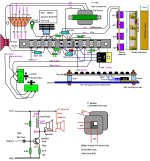
I have attached the diagram what I ended up with in my units with the DB9 connector. I doubt if anyone else would want to make this version, because it means having to have an impedance matching transformer to run an 8 Ohm or 45 Ohm speaker (in this case the design needs to keep the relatively low DCR of the choke to remain, even if the 45R speaker is used).
I enjoy making small transformers, but the parts now, like the laminations, bobbins and clamps are getting hard to get. I made these ones from some old filter chokes taken from defunct car radios. For the hookup wire I used Telfon covered multi-color wire that came out of a submarine. I like this wire a lot more than pvc, because the insulation doesn't melt or shrink back when it is soldered. In the Kraft radio control units, they also used Teflon covered wire.
This does make transformer-less pcb designs not only easier to make but often more efficient too, still I don't mind squandering a watt or two here and there !
Small signal transformers (aside from power transformers) all but disappeared from radio and TV designs by the late 1970's, but there are a few places where it is very hard to get rid of them, largely because of their core's magnetic energy storage properties. One application was the small driver transformer for the H output transistor's base-emitter circuit, in CRT TV's and VDU's, these normally remained in the design, until the CRT became completely obsolete by the year 2015. This is because the transistor's drive cycle depended on the stored energy.
Attachments
Last edited: