For everyone following my project, I have really great news!
I have done some testing with the 5170 reference mainboard since I wanted to exclude larger system areas from having issues. So I have removed the DRAMs, memory transceivers and a few other ICs from the refresh generator, created the memory card header from various points on the 5170, and I have done some testing. The result was that the 5170 worked perfectly with the memory card, showing the whole 2MB of soldered SRAMs on the board. I have run the 5170 for a few hours without a single crash. The 5170 didn't show any screen update issues, so I was certain that the memory card had no issues at all.
Next I proceeded to completely disable all REFRESH logic, and removed some ICs to more closely match the state of the 5170 to my prototype. All the software I ran on the 5170 worked fine.
I also switched off the system timer signal just to see the impact on the system, but this was not able produce any screen issues. At the most I found the system just waiting until I re-enabled the system timer and it continued as normal.
After that I decided to take some scope measurement screenshots of the CPU cycle control signals on the 5170, since the cycle control was working perfectly there. The 286 cycle control logic and byte conversion logic is in my view the most timing sensitive area of the whole AT system. So I decided to first look at the CPU cycle control since this also propagates into the byte conversion timings.
I powered up the prototype and started to probe the cycle control signals, where the first thing I noticed was that the /ARDY pulses looked rather short in the length of their positive phases. So the "not ready" states were looking a little on the short side compared to the 5170 scope images. I have a very cheap scope however thankfully I was able to find this from the measurements shown.
So after doing a few tests to improve the timing of /ARDY, I could immediately see differences in the screen update issues when I looked at the MR BIOS screen. I did a few tests to extend the /ARDY pulse duration by shifting it through an additional flipflop, finally, using the the inverted CPU clock and applying IOCH_RDY to the second flipflop as well, I got the system working without any screen issues! The problem which I have been looking at for a few weeks is now completely solved!
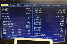
Apparently the problem was in the /ARDY operation of the System Controller CPLD where the timing at which the signal was switching was too fast for the 82284 and the 286 CPU. After fixing this problem I found a much more stable operation of the whole system. No more beeps from MR BIOS so far and the RTC is keeping the CMOS settings well, which results in a normal power on and proceeding to the boot screen right away.
So all the issues I have found so far were all able to be solved inside the CPLDs, which can really show their prototype design value! I don't need to change anything in the PCB layout.
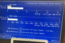
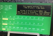
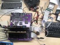
I have seen a huge improvement in the stability of the AT system since I fixed the cycle timing. Now it really looks like a fully stable AT PC. I will do further testing since I still need to test the onboard RTL8019AS LAN connection and SCSI adapter, I need to order some NCR 53C400 chips for that. Also I still need to program a serial EEPROM for the LAN chip configuration using a ISA adapter card and the configuration program. I don't have any supply of those EEPROMs so I will need to use the one I do have here. The DS12885 RTC is now working just as reliably as the MC146818 by changing two jumpers, so I am happy about that. The RTC is powered by the 5V standby power from the ATX PSU so it will not use any battery current as long as the power cable is plugged in and the back power switch is turned on on the PSU.
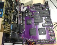
The prototype PCB is working really well above what I expected because I always considered that I might need to design and manufacture at least another revision of the PCB, however At the moment I don't see any reason to need to do this.
I will update the Github information with all the final CPLD JEDEC programming files and everything needed to build this AT design.
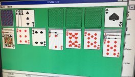
So now I will also start enjoying to test the system even more and play some games etc on it!
Kind regards,
Rodney
I have done some testing with the 5170 reference mainboard since I wanted to exclude larger system areas from having issues. So I have removed the DRAMs, memory transceivers and a few other ICs from the refresh generator, created the memory card header from various points on the 5170, and I have done some testing. The result was that the 5170 worked perfectly with the memory card, showing the whole 2MB of soldered SRAMs on the board. I have run the 5170 for a few hours without a single crash. The 5170 didn't show any screen update issues, so I was certain that the memory card had no issues at all.
Next I proceeded to completely disable all REFRESH logic, and removed some ICs to more closely match the state of the 5170 to my prototype. All the software I ran on the 5170 worked fine.
I also switched off the system timer signal just to see the impact on the system, but this was not able produce any screen issues. At the most I found the system just waiting until I re-enabled the system timer and it continued as normal.
After that I decided to take some scope measurement screenshots of the CPU cycle control signals on the 5170, since the cycle control was working perfectly there. The 286 cycle control logic and byte conversion logic is in my view the most timing sensitive area of the whole AT system. So I decided to first look at the CPU cycle control since this also propagates into the byte conversion timings.
I powered up the prototype and started to probe the cycle control signals, where the first thing I noticed was that the /ARDY pulses looked rather short in the length of their positive phases. So the "not ready" states were looking a little on the short side compared to the 5170 scope images. I have a very cheap scope however thankfully I was able to find this from the measurements shown.
So after doing a few tests to improve the timing of /ARDY, I could immediately see differences in the screen update issues when I looked at the MR BIOS screen. I did a few tests to extend the /ARDY pulse duration by shifting it through an additional flipflop, finally, using the the inverted CPU clock and applying IOCH_RDY to the second flipflop as well, I got the system working without any screen issues! The problem which I have been looking at for a few weeks is now completely solved!
Apparently the problem was in the /ARDY operation of the System Controller CPLD where the timing at which the signal was switching was too fast for the 82284 and the 286 CPU. After fixing this problem I found a much more stable operation of the whole system. No more beeps from MR BIOS so far and the RTC is keeping the CMOS settings well, which results in a normal power on and proceeding to the boot screen right away.
So all the issues I have found so far were all able to be solved inside the CPLDs, which can really show their prototype design value! I don't need to change anything in the PCB layout.
I have seen a huge improvement in the stability of the AT system since I fixed the cycle timing. Now it really looks like a fully stable AT PC. I will do further testing since I still need to test the onboard RTL8019AS LAN connection and SCSI adapter, I need to order some NCR 53C400 chips for that. Also I still need to program a serial EEPROM for the LAN chip configuration using a ISA adapter card and the configuration program. I don't have any supply of those EEPROMs so I will need to use the one I do have here. The DS12885 RTC is now working just as reliably as the MC146818 by changing two jumpers, so I am happy about that. The RTC is powered by the 5V standby power from the ATX PSU so it will not use any battery current as long as the power cable is plugged in and the back power switch is turned on on the PSU.
The prototype PCB is working really well above what I expected because I always considered that I might need to design and manufacture at least another revision of the PCB, however At the moment I don't see any reason to need to do this.
I will update the Github information with all the final CPLD JEDEC programming files and everything needed to build this AT design.
So now I will also start enjoying to test the system even more and play some games etc on it!
Kind regards,
Rodney