Bruce Tomlin
Experienced Member
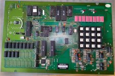
I've finally gotten around to trying to make some of my accumulated stuff work. The thing I'm working on now is a bare board from an early 1990s telemarketing dialer. The software has a 1994 date in it, so this would be shortly after the Telephone Consumer Protection Act of 1991 (TCPA). It was made by Kolker Systems Inc., which was one of the companies at the forefront of the auto-dialer brouhaha.
The board itself uses a 6802 CPU, which has the original 6800 instruction set, but adds 128 bytes of RAM. And it is packed full of stuff. There are four 6821 PIAs, for a total of 80 bits of I/O. It has 24K of ROM, 32K of RAM, a 4x4 keypad, an 8 x 7-segment display, a 6850 ACIA, a 6840 timer (which is also the baud rate generator), a DTMF generator, a voice recorder chip with additional bank switching for up to six times its normal capacity, and what appears to be two cassette tape controllers. And a 1 Farad supercap too, because why not?
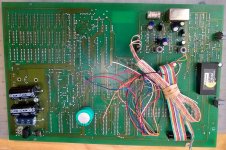
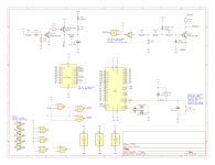
I found it with the cords chopped, but at least they were left connected. I was able to rig up a terminal block for the power. It needs 5V regulated, and 24 VAC center tapped. Of course the +/-12 volts is for RS-232 and some of the analog stuff, so I just hooked up a 5V 3A power brick. It also has no silkscreen, and having no designators is somewhat annoying when trying to build up a schematic. I've already got 8 pages of KiCad schematics just to rough out the big stuff, and none of the analog circuitry.
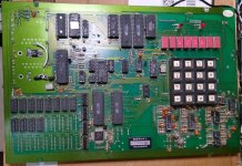
Of course when I finally applied power, nothing happened. I was able to tell that the reset line was stuck. The reset traces went three ways, so of course to narrow it down I ended up cutting the two that weren't the problem. The third one went under five chips, and was inverted through a 74LS00 NAND gate. So I lifted the 74LS00 pin (yay sockets). Since reset already had a pull-up to 5 volts, I added a capacitor, and a pushbutton for manual reset. That's the bodge on the left. I still don't know yet what is wrong with the original reset circuit.
The next problem was that it was running long slow tests, and would fail one of the RAM tests. I still don't know exactly what the problem was, but I was able to patch around it and a couple of other tests, and still couldn't get it to reach the main code. I was, however, able to write my own code to make the display work.
The next problem was that it was really picky about EPROMs. I tried some 2864 chips which seemed to have some bytes flake out after being used a couple of times. Oh well, I still have my 9-chip UV eraser. It also had problems with some EPROMS that I tried, and since the original was 120ns, I gave up on the 250ns chips that I was using, and picked out a bunch of 27C512-15 chips. I think there's also a loose connection on the board, because once or twice it failed to work even with the original EPROM installed.
The display uses a chip that does its own scanning, and I noticed that the decimal point wasn't working. Sure enough, it wasn't connected, but they left space for a jumper. So I hooked it up, and it turns out that the decimal point bit is inverted! No wonder they left it disconnected by default. I bodged in a jumper block for that.
At this point I need to figure out how to get the timer chip to generate a 9600 baud clock, and I'll probably bodge in a TTL serial-to-USB adapter so that I still won't need 12 volts. It would be nice to write some kind of trainer monitor for it, but that keypad is not great, and a good user interface is hard without more keys. (Heathkit used 16 keys plus reset on the ET-3400, and it's a pain to use!) A serial monitor would be better, because I could load code with it. I might even try to bodge in an external keypad just so I don't have to use this keypad. (It would also be nice to desolder that keypad for a photo, because it has a rats nest of traces going under it!)
The board itself uses a 6802 CPU, which has the original 6800 instruction set, but adds 128 bytes of RAM. And it is packed full of stuff. There are four 6821 PIAs, for a total of 80 bits of I/O. It has 24K of ROM, 32K of RAM, a 4x4 keypad, an 8 x 7-segment display, a 6850 ACIA, a 6840 timer (which is also the baud rate generator), a DTMF generator, a voice recorder chip with additional bank switching for up to six times its normal capacity, and what appears to be two cassette tape controllers. And a 1 Farad supercap too, because why not?
I found it with the cords chopped, but at least they were left connected. I was able to rig up a terminal block for the power. It needs 5V regulated, and 24 VAC center tapped. Of course the +/-12 volts is for RS-232 and some of the analog stuff, so I just hooked up a 5V 3A power brick. It also has no silkscreen, and having no designators is somewhat annoying when trying to build up a schematic. I've already got 8 pages of KiCad schematics just to rough out the big stuff, and none of the analog circuitry.
Of course when I finally applied power, nothing happened. I was able to tell that the reset line was stuck. The reset traces went three ways, so of course to narrow it down I ended up cutting the two that weren't the problem. The third one went under five chips, and was inverted through a 74LS00 NAND gate. So I lifted the 74LS00 pin (yay sockets). Since reset already had a pull-up to 5 volts, I added a capacitor, and a pushbutton for manual reset. That's the bodge on the left. I still don't know yet what is wrong with the original reset circuit.
The next problem was that it was running long slow tests, and would fail one of the RAM tests. I still don't know exactly what the problem was, but I was able to patch around it and a couple of other tests, and still couldn't get it to reach the main code. I was, however, able to write my own code to make the display work.
The next problem was that it was really picky about EPROMs. I tried some 2864 chips which seemed to have some bytes flake out after being used a couple of times. Oh well, I still have my 9-chip UV eraser. It also had problems with some EPROMS that I tried, and since the original was 120ns, I gave up on the 250ns chips that I was using, and picked out a bunch of 27C512-15 chips. I think there's also a loose connection on the board, because once or twice it failed to work even with the original EPROM installed.
The display uses a chip that does its own scanning, and I noticed that the decimal point wasn't working. Sure enough, it wasn't connected, but they left space for a jumper. So I hooked it up, and it turns out that the decimal point bit is inverted! No wonder they left it disconnected by default. I bodged in a jumper block for that.
At this point I need to figure out how to get the timer chip to generate a 9600 baud clock, and I'll probably bodge in a TTL serial-to-USB adapter so that I still won't need 12 volts. It would be nice to write some kind of trainer monitor for it, but that keypad is not great, and a good user interface is hard without more keys. (Heathkit used 16 keys plus reset on the ET-3400, and it's a pain to use!) A serial monitor would be better, because I could load code with it. I might even try to bodge in an external keypad just so I don't have to use this keypad. (It would also be nice to desolder that keypad for a photo, because it has a rats nest of traces going under it!)