• Please review our updated Terms and Rules here

Has anyone worked with the Model I keyboard circuits?

Tuc

New Member
Joined
Oct 3, 2023
Messages
4
Hi,

Me again. ;) I'm interested in trying to set up a KVM to a TRS-80 Model I. The video is "Component" which I should be able to use generally available consumer items to get into HDMI (Maybe not the most PERFECT picture, but won't need to be 4K ;) ). Its the keyboard part I'm wondering about.

I've been trying to read the schematics, but really not an electronics person (anymore, used to do all that 40+ years ago so I have a 1/4 clue but that's about it) so its a bit difficult. I realize tapping into the 8x8 matrix won't be the best way, trying to find where/what chip is the recipient of it all and see how to interface with that or where it outputs it to elsewhere. I see a lot of people talking about the "Teensy" to do something like this so once I do so may check that out.

BUT, if anyone's gone down this road before and has hints, tips, or "Its a rabbit hole" I'd be appreciative.

Thanks!
Tuc
 
I can relate. Back in April of this tear, I wrote the attached "article". Perhaps you or others might find it helpful. Be warned, however, I write these things very much tongue-in-cheek. They get sent to a few friends that seem to get a kick out of them. Also, they are usually NOT about electronics; fixing a towel rack; gear shifter; a war with the ants...and more. Hey, it's fun. Also, there is absolutely no responsibility on my part if you are foolish enough to listen to me :)

Hope it helps.
 

Attachments

  • The Case of the TRS80 Keyboard.pdf
    4 MB · Views: 19
  • Like
Reactions: Tuc
Typically the results of the keyboard scan are returned in the accumulator of the Z80 CPU. In other words, it’s all internal to the CPU. It doesn’t really exist as something you can pass through a KVM.
 
Last edited:
  • Like
Reactions: Tuc
, trying to find where/what chip is the recipient of it all and see how to interface with that or where it outputs it to elsewhere.

The "recipient" of the keyboard matrix is the Z80 CPU; the TRS-80's keyboard is scanned entirely with software, there's no intelligent decoder in there at all. The keyboard is memory mapped and effectively occupies 256 bytes of memory at the 14K mark. (*) The 8 row select lines are literally just the lowest 8 address lines of the CPU, and during the keyboard scan the CPU reads 8 addresses spaced a power-of-two apart, which generates the "strobe" that places a bitmap of the 8 keys on that row on the data lines.

A fluke inherent in this design that makes it particularly tricky to put some kind of decoder for an "intelligent" keyboard in place to emulate the matrix is the CPU can technically read more than one row at a time; out of the 8-bit address space covered by the keyboard only 8 addresses strobe a single line, all the rest will strobe the binary combination of nodes, and in response to that the byte that's returned by the read will be logical OR of the state of the down keys on any of the rows. For instance, with this layout you can tell if *any* keys on the keyboard are down by reading the 255'th address (which strobes all the rows at once); if any bits are set then you know there's a key down *somewhere*. This makes it a little harder to make a matrix coder than for, say, a Commodore machine, which have one-of-X decoders in front of the matrix so only a single line can be strobed at once.

The "standard" solution for this is to pair a microcontroller that speaks PS/2 or whatever with an 8x8 analog matrix switch array IC like the MT8809. These parts essentially will let you create a microscopic "virtual keyboard" where the state of every switch crossing can be updated by the MCU based on the decoded keyboard scancodes. If you dig around there's at least one existing design out there using a PIC microcontroller to drive the matrix switch, but if you want to do it yourself PS/2 keyboard scan libraries for Arduino are a dime a dozen, shouldn't be too hard to cobble it together.

Doing it without the matrix switch is "possible", but if you want to accurately emulate this "more than one row scanned at once" behavior you'll need a pretty fast MCU that's capable of reading all 8 address lines and outputting a logical OR of any of the selected ones based on an in-memory representation of the keymap inside a Z80 memory read cycle. That's about one microsecond, give or take, at the TRS-80's clock speed.

(* Technically the keyboard occupies the whole 1K of memory between 14K and 15K because it's only partially decoded; there's 4 copies of it between 3800-3BFF. But the "canonical" mapping for it is 3800-38FF.)
 
Last edited:
It's all done in software. Any other "chip" would make it cost more. Your only two options are 1: set up an Arduino or something to watch the scan row address (yeah, ignore the multiple selects, nobody used that) and immediately force the column inputs through diodes, or 2: patch the ROM code to allow ASCII codes from something external, but that would fail at anything that checks for the shift key, etc. by simply reading a matrix address. Or yeah, 3: a switch matrix chip.
 
  • Like
Reactions: Tuc
set up an Arduino or something to watch the scan row address (yeah, ignore the multiple selects, nobody used that) and immediately force the column inputs through diodes

I would swear I've seen that "see if any keys are held down on multiple rows" trick printed in contemporary TRS-80 literature, but, yeah, I imagine a device that only outputs one row (maybe the lowest set address line?) would work fine for at least three or four nine's worth of TRS-80 software.

The main advantage of the matrix switch is really that it lets you do everything completely asynchronously; you don't have to worry about responding to an interrupt or whatever instantly and outputting the right data byte in a tight window, you can update the switch matrix completely at your leisure as you respond to keystrokes and as long as your latency isn't more than a few milliseconds any lag isn't going to be perceptible.(*)

(*Edit: The Raspberry Pi Pico has those interesting GPIO acceleration features, I vaguely wonder if they could essentially emulate the behavior of the matrix switch completely hands off from the main CPU core. That could make for a neat option if you wanted to use a USB keyboard...)
 
  • Like
Reactions: Tuc
I'm interested in trying to set up a KVM to a TRS-80 Model I. The video is "Component"

Composite. Although, since it's monochrome, I guess it should be equivalent to the Y in YPbPr component.

(Yes, these terms are often confused. Both are valid types of video output.)

The monitor connector on the Model I carries both composite and 5V, to drive the opto-isolator of the (U.S.?) standard monitor. See: https://forum.vcfed.org/index.php?threads/model-i-monitor-as-composite-monitor.74355/
 
This is a really interesting thread. I am interested in developing a joystick port (up/down/left/right/space), that can also potentially act as a USB keyboard port, so I've been studying what everyone has said. I've spent some time over the last couple of days doing a further deep dive on this.

I've come up with a fancy way to do it, and the more obvious brute-force way. I have come to feel that the brute-force way is better, am interested in people's thoughts.


My goal is to provide a little board that interposes between the existing keyboard cable and the keyboard, that allows simultaneous use of either the stock keyboard or the external joystick and keyboard.

I'd like it to be microcontroller-based so that it can do things like acting like a keyboard, or dealing with other kinds of joystick encodings. One can also imagine automating test sequences that are more expansive than any one software package, like "Boot into this FreHD partition then..."


MT8088 Approach
The short summary is I think I'm going to go with the MT8808 approach:
  • Pro: It has internal registers that remember the state of every switch. As mentioned by Eudimorphodon, this means that you don't have to time what you're doing to the keyboard scan.
  • Con: When powered from 5V, the on resistance of the switches is quite high, as high as 225 ohms.
  • Slight con: It's an older chip and is addressed in parallel (9 pins in all) rather then over I2C or SPI. That actually makes it a little easier to program at the expense of more pins.
The 225-ohm on resistance was a significant concern to me, but I think it's okay. Back to that in a moment.


RP2040 Approach
Using a Raspberry Pi Pico, or a RP2040 Zero or the like, there is plenty of horsepower to make all the decisions one needs to make in a fraction of a microsecond. The software part seems pretty easy (even for multiple simultaneius key presses), but the hardware is tricky.

The tricky part is, how does the RP2040 detect when the column scan lines go low? The problem is that, unless a key is pressed, the state of the scan lines is indeterminate, because they are driven by open-collector 74LS05's and there is no load resistor on the line unless a key is pressed.
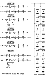
1714526165891.png

So you can't simply hang a microcontroller off of them and read the scan lines. You have to add a pull-up resistor. Fine, the RP2040 has internal pull-ups. But they are in the 50K-80K range. If you assume perhaps as much as 100pF of capacitance on the line, you end up with an 8us time constant and 25us rise time, way too slow to meet the 1us requirement that Eudimorphodon has called out.

So you have to provide a strong pull-up. Not surprisingly, if you run the numbers, you end up at something like 1.5K being a good value, which turns out to the be the value that the TRS-80 actually uses in its design. But
  • The stock pull-ups only are active and consuming power when an associated key is pressed
  • If you have two 1.5K pull-ups, you're pulling 3.3mA through all of the LS05 outputs all the time, and 6.6mA when a key is pressed. The part is rated for 8mA max. So it's okay, but I'd rather not burn all that power all the time, and it's exercising the LS05 in a regime under which it was never tested in the TRS-80.
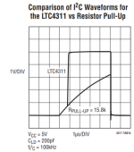
I decided on instead using 20K resistor together with a MAX20326 I2C bus accelerator (the LTC4311 is another option but is pricey). Each chip only does two pins, so you'd need four of them, but they are tiny. These are smart devices that sense the initial rising edge and then turn on an active pullup. Then you end up with this sort of thing. Assuming the RP2040 is powered from 3.3V, you'll need a diode to protect its input, but it's not bad.
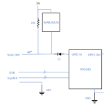
1714527219054.png 1714527254420.png

So now you can scan the keyboard.

On the output side, at first I was just planning on driving the lines with open collector buffers, but you run into a second issue which is "when do you actually let go of the output scan line?" There's a possibility of driving it for too long. You need to first wait for your active pull-up to notice that the input scan line has been released, then for it to pull the line up, then for the software to notice it, then you have to turn off your gate. There might be a good fraction of a microsecond delay from when the LS05 releases the line to when our scan line driver actually releases it. Only then will the stock 1.5K pull-up begin its work of charging the line back to 5V.

So I tried adding my own active pull-up to the output of my open collector gate, and realized that I was actually building a CMOS gate out of parts. So I realized that what was wanted was a tri-state output instead. If one is using a 5V microcontroller, this can come from the micro itself. With a 3.3V device, one would use something like a 74HCT125. So just showing a couple of the output lines, it looks like this.
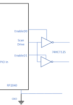
1714527634209.png
What happens here is that
  • Normally all the Enables are off.
  • When an input scan line goes low, we set the "Scan Drive" output to 0 and then assert whichever Enables are appropriate
  • When the input scan line goes high, we set "Scan Drive" to 1 briefly. This is our "active pullup".
  • After 250ns or so (or if we see a new scan line go low), we reset all Enables to off.
It gets a bit funky when multiple scan lines turn on at once. I think that might all work, but it's really pretty complicated.


Back to the MT8088
So after all that, I looked more deeply at the specs for the receiver chip. Curiously, the TRS-80 designers don't feed the keyboard matrix directly into the 74LS240 that buffers the results onto the data bus. Instead, they send the signals first through a MC14050B, a CMOS device.
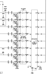
1714527993759.png

One assumes that this is done for noise immunity reasons. The logic-low threshold for the device is 1.5V as opposed to TTL's 0.8V threshold.

That turns out to be good news for the MT8808 approach. Even with a 250-ohm on resistance, it should be capable of pulling the 1.5K pull-up down to 0.7V. That might be iffy with a TTL input, but is in the happy space for the CMOS device.


So, I'm thinking MT8808. It's an old device, but Digikey happens to have some stock right now, and Mouser as well. Those are PLCC's. DIP versions are available on AliExpress. There is a more modern device, the Analog Devices (Maxim) MAX14724ETP+. It's an 8x4 array not 8x8 so it would take two of them, but it is programmable via I2C or SPI and is easily ganged, and has a better on resistance. However, it's only available in TQFN, and it seems to really prefer to operate off a bipolar power supply.

Certainly the MT8808 makes the microcontroller a lot less busy. You don't need the horsepower of a RP2040 so could use a 5V device, which is kind of what you want to use with the MT8808 anyway.

UPDATE: I did a quick test and "shorted" two of the scan lines with a 300-ohm resistor. I got keypresses. So MT8808's on resistance should be fine.


Thoughts? Any reason to think that that's the wrong answer?

Thanks,
Brad
 
Last edited:
It's too late for me to read that and think at the same time. But, I was reading this earlier today after reading a recent thread here.


and wondered if you had seen it/

Thanks, that's an interesting project!

I puzzled over it for a while trying to figure out how they could do this with no hardware other than the micro. It finally occurred to me I think it may be doing the opposite of what I want to do.

It appears that you unplug the keyboard from the motherboard and plug it into the microcontroller, and then you plug the micro into the computer's USB port. Cool. And a useful code base to study as well.
 
Really, you need to check the schematics before you do stuff like this. As you already learned from pulling that earlier wire, things are often there for a reason. In this case, how do you know that this wasn't merely a capacitor trimmed for a position where 0.075 μF was needed? :-)
 
I would swear I've seen that "see if any keys are held down on multiple rows" trick printed in contemporary TRS-80 literature...
I am pretty sure that I've seen that, too. Possibly even in the TRS-80 ROMs or something related, though looking back, I can see I never got around to disassembling that bit of the Model I Level II ROMs.

The "standard" solution for this is to pair a microcontroller that speaks PS/2 or whatever with an 8x8 analog matrix switch array IC like the MT8809.
That's normally my recommended solution, too, for things like joysticks or "generic" keyboard emulators where you're not always exactly certain about what circuitry is being used to scan the switches. But in this case we know exactly what the circuit is and how it works, so I have the feeling (Eudi will correct me if I'm wrong here) that you could do it with a fairly cheap microcontroller so long as you've got
  • 8 output lines you can quickly set and tristate, directly driving the data bus;
  • 8 input lines for the row select, directly reading the low 8 bits of the address bus
  • and at least one more for the keyboard read select logic (you can use a bit of external decoding for the upper 8 bits of the address, /MEM, /RD, etc.).
The trick to getting the correct output on the lines quickly is to keep a table of all 256 possible values that you might need to output based on the 8 bits of row select input. As soon as you're selected, you can read an index into the table from the address bus inputs, load the value at that index from the table, and send it out the output lines.

The extra work of "ORing" together all the appropriate values for selected rows actually happens when you receive an HID packet (if you're using USB or Bluetooth) or a serial key press/release notification (if you're using PS/2 or whatever) from the external keyboard: you then OR that into all 128 of the table entries that could activate that row (or AND it out for a key release).

This is a fair amount of work per key, but the thing about that is, so long as you have a human typing, you're not really doing it that often, not nearly as often as the TRS-80 is scanning the keyboard.
 
Wow, didn't think this would get picked up again.

As for Marcels device, yes, it only allows your TRS-80 to become a USB keyboard to something else. I've asked if he was planning to be able to inject into the TRS-80, and at the time he wasn't. (But knowing him....)

I actually ended up finding out about "NewKey/80 Ultra", and the creator even created a single board version of it. It does Keyboard and Joystick. (https://www.plaidvest.com/newkey80.html - I know it only talks about the 3/4, he didn't sell many 1's so he stopped putting it on the site, but he did recently create a whole new version just for the Model I and I've tested it out) . The only thing you do is cut the *KBD line and put a toggle switch in it. ON, it works like a normal keyboard. OFF, you want to use the NewKey/80. It then attaches to a ribbon cable out the back of the MI and before the EI. a bit of power and you're golden.

Tuc
Wow, that looks very much like the device I was thinking of making, this is great! A RP2040 with a MT8808!

It looks like it's intended to be used in place of the existing keyboard rather than in addition to? Definitely indicates that the idea will work. Looks like you basically just need to add the second connector in parallel.

I like the wireless keyboard idea. That's quite slick. I had been mulling over how to get the leads out - was going to bring them out on a SIP header through one of the slots in the bottom of the system. But instead one could have a wireless link to a second microcontroller. A really enterprising person could even put that *inside* the joystick.

So you could have a wireless keyboard, or a wireless joystick.

I wonder if the NewKey/80 developer would be interested in collaborating on an update.

This is an excellent tip, thanks. I'll reach out.
Hi,

You can't have both active at the same time. Either you have the *KBD signal active and the TRS keyboard works, or you cut off the *KBD signal and the NewKey/80 works. He suggested never to try to have both active, and I took that suggestion. :) But it works great. And it plugs into a supplied cable that has an extra pin header between the MI IDC and the EI IDC. I had some issues with my gaming keyboard which he could never figure out, not sure if wireless would suffer the same fate. (Though this gaming keyboard has had issues with certain KVMs, Rack Servers, the NewKey/80 and some other things - And those were all wired!)

If you need help contacting him, lemme know. I keep in touch over a Tandy Discord.

Tuc
 
The extra work of "ORing" together all the appropriate values for selected rows actually happens when you receive an HID packet (if you're using USB or Bluetooth) or a serial key press/release notification (if you're using PS/2 or whatever) from the external keyboard: you then OR that into all 128 of the table entries that could activate that row (or AND it out for a key release).

Of course, yeah. I think this idea of pre-calculating all 256 possible values did occur to me but I think I might have discarded it because I was thinking of a tiny RAM limited potato chip of an MCU doing the keyboard handling. It should be reasonable with almost any modern MCU to calculate the whole OR table upon processing the keyboard strobe.

The one proviso I might chuck out here is you are still going to have to have an MCU that's fast enough to deal with the ~1 microsecond-ish window you have to respond to a read of the keyboard matrix; there's no busy line we can pull to make the Z80 wait. (That is the beauty of the matrix switch, it takes this problem of responsivity out of the loop.) An RP2040 is fast enough to handle this, but I kind of wonder if it might not be a terrible idea to actually keep 2 copies of that or-table in memory and switch the "read handler" between them so updates to the matrix can be completely atomic. (Or, I dunno, maybe that doesn't matter. I mean, I guess in either case you're either going to get the fresh state or a potentially stale one if a scan comes in the middle of a table update; you should catch up anyway the next time the TRS-80 scans the keyboard.)
 
  • Like
Reactions: cjs
Hi,

You can't have both active at the same time. Either you have the *KBD signal active and the TRS keyboard works, or you cut off the *KBD signal and the NewKey/80 works. He suggested never to try to have both active, and I took that suggestion. :) But it works great. And it plugs into a supplied cable that has an extra pin header between the MI IDC and the EI IDC. I had some issues with my gaming keyboard which he could never figure out, not sure if wireless would suffer the same fate. (Though this gaming keyboard has had issues with certain KVMs, Rack Servers, the NewKey/80 and some other things - And those were all wired!)

If you need help contacting him, lemme know. I keep in touch over a Tandy Discord.

Tuc

The concept of a wireless keyboard really set my head swirling with possibilities. Suddenly the "right" solution seems so natural - Bluetooth. This is exactly the sort of thing it's made for.

Inside the TRS-80 you have just the MT8808 chip and a ESP32-C3-Zero. The MT8808 is wired in parallel with the existing keyboard matrix.
1714604536267.png
There are no external wires, except during programming/debugging.

You can connect to it with a Bluetooth keyboard, and/or... a Bluetooth gamepad! I can just use my wireless XBox controller (the kind that can pair with a PC). Apparently they talk Bluetooth via a classic HID profile, or HID over GATT with Bluetooth LE. Now that gives us a world-class gaming device, and no wires. Of course if someone wants a retro joystick, one can make a dongle with a DB9 using another ESP-32C. But don't they just look like they go together?

1714605154303.png 1714605095111.png

But even more cool, there are all these additional buttons on the controller. So one can construct mappings for different games. (It is probably possible to forge another serial Bluetooth link with a PC and talk to it like a serial port, to either select profiles, or upload them. I know it's possible for PC's to talk serial over Bluetooth, I'm just not sure if the PC can act as a peripheral, or if it can only be the central node.)

I just sprang for $2.50 each for a pair of the ESP32's and also a MT8808 from AliExpress. I'll prototype something up when they get here and report back.

Brad
 
Of course, yeah. I think this idea of pre-calculating all 256 possible values did occur to me but I think I might have discarded it because I was thinking of a tiny RAM limited potato chip of an MCU doing the keyboard handling. It should be reasonable with almost any modern MCU to calculate the whole OR table upon processing the keyboard strobe.
Yeah, given that you're going to need 18-20 I/O pins anyway, and it's got to be something you can actually purchase (oh MC68HC11 how I miss you) I was reckoning the usual mid-size AVR thingie. So you're going to have 512-2048 bytes of RAM, as well as far more flash than you need.

The one proviso I might chuck out here is you are still going to have to have an MCU that's fast enough to deal with the ~1 microsecond-ish window you have to respond to a read of the keyboard matrix...
The interrupt response time on an ATmega32 is 4 cycles, I hear, so assuming another six or eight to read the address lines, look up the data, and shove it out on the data lines you should have your data out in less than a microsecond if you're running at the standard 16 MHz most people use when running at 5 V. Or so my theory goes, anyway.

...I kind of wonder if it might not be a terrible idea to actually keep 2 copies of that or-table in memory and switch the "read handler" between them so updates to the matrix can be completely atomic. (Or, I dunno, maybe that doesn't matter. I mean, I guess in either case you're either going to get the fresh state or a potentially stale one if a scan comes in the middle of a table update; you should catch up anyway the next time the TRS-80 scans the keyboard.)
Yeah, I thought about that too, and then thought,"Meh, not necessary." But now that you bring it up, I'm thinking about it again. But no, I don't think it's necessary for the table to be consistent with itself (i.e., a key up or down is consistently up or down in all bytes in which it appears) since only one byte is read at a time, and so any software has to expect that a read of one byte immediately followed by a different one may see the key up in one and down in the other because that actual key could have changed its pressed/released state between those two reads.
 
The interrupt response time on an ATmega32 is 4 cycles, I hear, so assuming another six or eight to read the address lines, look up the data, and shove it out on the data lines you should have your data out in less than a microsecond if you're running at the standard 16 MHz most people use when running at 5 V. Or so my theory goes, anyway.

The interrupt latency can vary by one clock tick depending on CPU state. Looking at the timing diagram for a memory read on the Z80 it actually looks like we’re probably closer to around 800ns to get the data on the bus and stable (if it were an instruction fetch it’d be more like 500ns) so… maybe. The I/O pins essentially look like cpu registers so you wouldn’t have to do an explicit “in” to read the address lines, so the response is going to be “add (input port register) to (table base), copy memory at (result) to (output register)”. Adding an 8 bit register to a 16 bit address is 2 clocks… yeah, maybe it’s doable. If your TRS-80 has a speed up mod, maybe not. (1.77mhz is very slow by Z80 standards.)
 
  • Like
Reactions: cjs
Back
Top