• Please review our updated Terms and Rules here

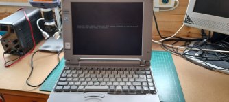
Toshiba 110cs Rip...

Damn Mark, I know how that feels. I'm unsure how to proceed with the 110 without removing chips and connectors where the corrosion hides. Keyboard connector is the worse I think, along with the controller.
Screen has died from capacitor problems too I'm sure. The 110 boots sort of, flashing hdd light, keyboard light then hangs. No external keyboard or monitor works. Wondering if a couple of caps on the power rails have failed too. There's a 100uf smd cap and a 56uf through hole cap that could be suspect.
My fdd doesn't show signs of life either but that has 2 caps and a tantalum sat on it.
Hope you can clean and salvage the 100ct, would be a shame to see it bite the dust.
Good luck. 😁👍
 
They could always be given a second chance at life and become a static museum exhibit.

Mine served as a useful serial terminal. It rorked very well with having a real rs232 port and being smaller than a laptop.
 
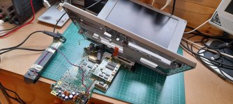
So... still picking away at the 110ct and 210cs after both suddenly stopped working.
Cleaned and messed about with the 110 and got it working... yay!... Well, sort of..
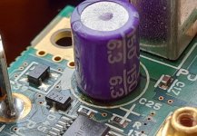
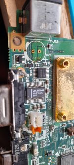
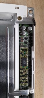
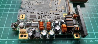
I'd never gotten the lcd screen working before so recapped the lcd powerboard as I noticed gunk and funky cap leg solder.
20240310_113552.jpg
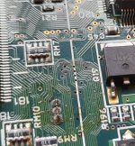
Motherboard out, rechecked corrosion, cleaned out veers, checked them and rebuilt it again.
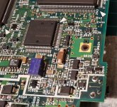
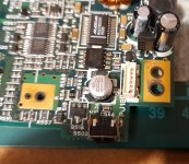
20240513_204312.jpg20240513_204423.jpg
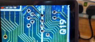
Plugged the screen in and ta-da!..20240514_105438.jpg20240514_133246.jpg
My problem now is what does this mean??
It did this on both machines before they stopped working.
Has the 5.20 bios become corrupt? Is it a sign of still more corrosion?
I have attached an external keyboard as the wafer thin flexi on the internal keyboard is beyond repair really but all I get on the ps2 keyboard is all 3 led's flash,( caps, scroll and num lock), then nothing. I've reflowed the ps2 keyboard connector pins but think I may need to check flexi cable connector pins for continuity incase I have trace damage. I read that the external ps2 connector runs through the onboard keyboard connector and can be temperamental.
----‐-‐-------------
Still working on the 210cs, swapping caps, cleaning veers etc..
20240515_191216.jpg
20240517_122347.jpg20240517_122802.jpg20240517_165547.jpg
and may have made progress on that one too. Downside is I recapped the dstn powerboard but shortly before it stopped working while displaying the same message I have on the 110ct, the dstn started to flash and flicker before going black. I've taken a look and need to recap 6 smd capacitors I think.
20240405_125117.jpg
It's either failed caps on the screen or the backlight blown. I have tried using a torch to see anything but it's just black so I'll cap it first I think. Not got any smd replacements so may be small through hole caps used and lay flat. Kapton tape will stop any shorts for testing I'm sure..
Thanks for any input as I try and save these old Toshiba classics.
 
great persistence!

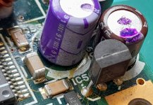
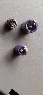
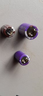
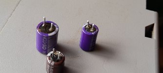
The purple caps are solid polymer, not electrolytic. They can’t leak and very rarely fail. If you see corrosion around one, it came from somewhere else. Swapping out the real electrolytics is a good move though.
 
The ones I swapped out had leaked out the bottom. Round the edges and legs.. I doubted they had leaked but something had upset them enough to get gunky etc.. I'm guessing the battery corrosion may have helped them go funky..
 
It had to have come from elsewhere, there is no liquid in those capacitors to leak. Failed? Maybe? You'd need a tester. But they can't leak.
 
I stuck them in the cheap tester I have. Slightly higher than rated, maybe 10-20%, esr was up and down but this changed everytime I run a test. Battery was good on the tester but it is the usual cheap tester. I just think battery gunk messed them up. Still unsure of that message on screen. I'm just hoping I can get them to at least function everytime I boot them up and display a bios at least.
 
Yes and no... lol.. it tries but the belt is stretched and misshapen. I've fit a new belt but it isn't right and needs doctoring. Thinking of dropping the old belt in boiling water to see if it will reshape and work again and refit that. The new belt is too thick and comes off after a short while. I have the bios update and a working base unit with a floppy drive to create a bios boot disc. I'll work on the floppy unit belt and see how it goes.
Thanks for the input.
 
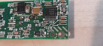
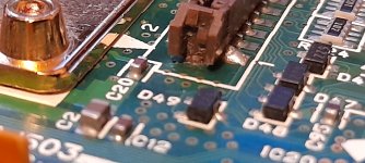
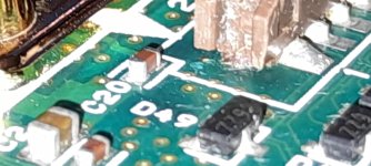
Just sharing these gunky legged chips.20240518_121712.jpg20240518_121727.jpg20240518_121735.jpg
I know the purple ones shouldn't leak but something upset them and caused corrosion and juice under them.
Anyway I changed them out and now the 210cs does this thing that resembles a start up.
It gives me power on light, after a seek type pause it starts the hdd power up but as I still have no display, no keyboard and only a broken clunky hdd I cannot tell what it's doing.
What I did find was 2 broken wires on the display harness from the graphics board. The wires go to the variable brightness wheel via the screen. I've swapped the harness but still no joy so the replacement harness might be wired different or it is them smd capacitors on the screen as mentioned before.
As for the original fdd belt problem, being damaged and misshapen I dropped it in boiling water. Unfortunately after it had cooled it fell apart all rotten and brittle.
20240518_121756.jpg
I'll keep picking away at these until I get a boot to bios and hdd seek. Things we do to play old games and relive our youths.. lol.. oh, and learning new skills along the way.
Thanks for any input vcf community..
 
Those purple Sanyos are awful. Even if they don't leak, they fail internally, usually by lost capacitance or high ESR. Sometimes they become electrically leaky, the polymer types are no better.
 
So... just looking for advice again. This time it's my temperamental 210cs. Now as stated months ago I managed to get it to partly come alive. I've run bodge wires in vias where continuity was lost, recapped the power, the screen and the display daughterboard. Checked the screen on another toshiba and it worked so ruled that out.
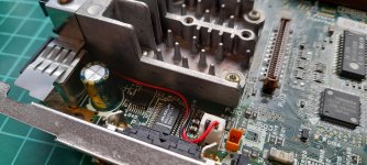
Plugged in a diagnostic card to the lpt 25pin port to get codes.. it gave 00's 01 and ff in different orders and confused the hell out of me. I reflowed some loose pins, and reflowed the hp187 chip. Reflowed the external keyboard port and changed the capacitor. Replaced a cap on the underside of the board and removed and cleaned out what was left of the corroded battery connectors incase I was getting a problem around them.
.... and still it gives a power led, a power on led followed by a hdd seek led and drive spin up but still no boot, no bios, no internal or external display. Nothing seems to be getting told to turn on and run etc..
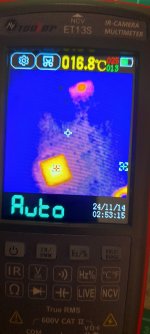
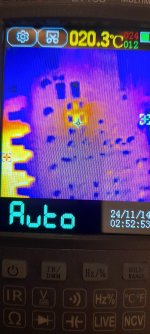
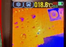
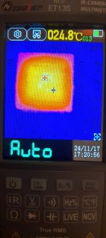
In desperation I've purchased a cheap thermal cam. It's the Et13S so nothing fancy but I purchased the lens with it and gave it a whirl..
20241113_185443.jpg
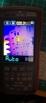
Right there you can see that the 187 chip gets power and warms to 20+ degrees along with the cy2292SC chip which distributes power I believe. The Maxim chip that sit infront of the external keyboard connector warms too. Also 2 resistor packs near the external vga port show signs of life as they start to warm.
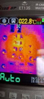
Now the underside of the board is near dead apart from the ic controller near the external vga and this resistor..
20241113_185429.jpg20241113_185418.jpg
This is near the underside of the 2 pin connector the power comes in on but I haven't a clue why just this one resistor glows..
20241113_190001.jpg
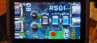
R501 it's a 3601 resistor . A 3.6k ohm smd with 1% tolerance.
So have I found a faulty chip, could this be stopping my boot? I don't have a replacement 3.6k ohm only a 3.3k ohm which would be too far out of spec I'm guessing.
As a quick check has given me a near correct reading of 3.576k ohm I'm wondering if it's the power input causing an over voltage burning out the resistor. Guess it's gonna be a try it and see.
Any input greatly received.
Thanks for looking.
 
If the resistor is getting excessively hot and it measures fine, whatever it is in circuit with is likely going to be the problem, not the resistor itself.
 
So I'm hunting up and downstream of the resistor for possible shorts maybe? Wondering now if my bodge wires through vias are connecting board layers? I'm not getting any hot spots around the vias or repairs though.
Just a warm 187 chip on the front which following Thermal wrongs posts over on Vogons is most likely my keyboard controller and due to corrosion in the keyboard connector can go down. I have a spare off the 110 board and an ALPs chip, higher version though.
It would have been nice for it to have just been the resistor.. oh well, I'll go hunting a bit more.
Thanks for the input. Oh, I did check the resistor while in circuit but it was so close to it's printed value I doubt it'll test different if I remove it.
Thanks again, shout up if there are anymore ideas or suggestions. Appreciated.
 
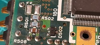
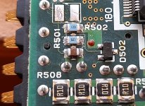
So another poke around today.. The 210cs has no real manual user or service to refer to for fault finding. Essentially the 210 is a poor man's 430 I believe, same motherboard, audio board graphics, processor etc.. so when I check my findings the only close reference is the baby brother 110cs board. I really need a 430 to compare chips, etc.. with as the power in where I'm testing is slightly different on the 110.
20241114_104800.jpg
The values are different and the power traces are different.
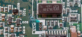
Above is the 210 area where heat is showing.
The 2 pins next to the R508 lettering are the connector for the power in from the internal psu. On the 210 the positive line goes left pin, left side of that unlabelled cap, right side of the warming resistor at R501 then back to left test pad above R502 resistor.
The pins look like they need a reflow and the unidentified cap looks scratched or cracked and gives no indication of capacitance.
On the 110 the board looks similar but the positive power rail runs left pin, left side on an identified cap C5 something or other, the LEFT side of the resistor R501and the left test pad. Again the capacitor on the 110 gives no reading.
So slightly different but no values found to aid in replacing cap or resistor. I guess I need a man with a 430 motherboard for readings and values.
20241114_110005.jpg
It's definitely the R501 resistor warming up.
Is that small cap damaged and causing no power on the rear of the board?.
Any ideas? Thanks again for any input.
 
.... and... maybe a thermal camera was a bad idea.. lol.. as I moved my thumb while doing some more thermal investigations tracing up stream of that resistor and lo and behold I find another warm resistor20241114_182550.jpg
It's this area..
20241114_183538.jpg
On the rear of the power switch.
20241114_183559.jpg
All values again are spot on and the resistors linked to it.
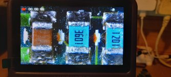
I got the other resistor area under the microscope..
20241114_173205.jpg
Can see the tiny traces and maybe that cap was just scratched and dirty as I cleaned it and it didn't look as bad.
20241114_172925.jpg
So maybe a couple of warming resistors is normal, I'm guessing not but I don't know what else to check. Thermal camera back in its box, multimeter back out I suppose tracing the power to find the fault.
Thanks again for checking post number 3 today as I share my findings. Maybe I'll get a simple fix one time.. lol.. more soon I'm sure.
 
So another poke around today.. The 210cs has no real manual user or service to refer to for fault finding. Essentially the 210 is a poor man's 430 I believe, same motherboard, audio board graphics, processor etc.. so when I check my findings the only close reference is the baby brother 110cs board. I really need a 430 to compare chips, etc.. with as the power in where I'm testing is slightly different on the 110.
View attachment 1289628
The values are different and the power traces are different.
Above is the 210 area where heat is showing.
The 2 pins next to the R508 lettering are the connector for the power in from the internal psu. On the 210 the positive line goes left pin, left side of that unlabelled cap, right side of the warming resistor at R501 then back to left test pad above R502 resistor.
The pins look like they need a reflow and the unidentified cap looks scratched or cracked and gives no indication of capacitance.
On the 110 the board looks similar but the positive power rail runs left pin, left side on an identified cap C5 something or other, the LEFT side of the resistor R501and the left test pad. Again the capacitor on the 110 gives no reading.
So slightly different but no values found to aid in replacing cap or resistor. I guess I need a man with a 430 motherboard for readings and values.
View attachment 1289629
It's definitely the R501 resistor warming up.
Is that small cap damaged and causing no power on the rear of the board?.
Any ideas? Thanks again for any input.
Yep the Satellite 210 is definitely based on the Satellite 430's mainboard and was the cheaper option of them.
Get yourself the Satellite 420 maintenance manual: https://www.minuszerodegrees.net/ma...te 420CDS and 420CDT - Maintenance Manual.pdf
The 420 is the same as the later 430 / 210 models and there's some very useful information in the maintenance manual. Specifically page 29 of the PDF has table 2-1 which lists what the codes on the parallel port mean. (oh it looks like there's a 430 maintenance manual too, I thought there wasn't)

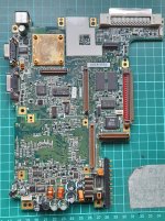
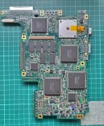
Thermal camera can give all sorts of false leads :) I did take some pictures and a scan of a Satellite Pro 430 motherboard which you can see here

Find out what the code it gets stuck on is first as that could guide what to do next. Did you replace those caps in the power section? It was probably just that Elna cap that had leaked and the purple caps were probably okay, but cap juice can cause all sorts of problems if not cleaned, I recapped a Toshiba SCSI CD-ROM and even though I did it right and cleaned as well as I could, it wouldn't read discs. Putting the PCB into the ultrasonic cleaner got it working though, so clearly some cap juice had remained in an important spot until being washed out.

I've been trying to get various Toshiba Satellite 400 to 430 platform motherboards working for a while: https://www.vogons.org/viewtopic.php?p=1163112#p1163112
Though that was mostly just replacing the lower mainboard a lot of the time - the motherboard of the satellite 200 & 210 is interchangeable with the 420 / 430 (PCI platform), though not the 400 / 410 (Local-bus platform) or later 440 / 220 series onwards as those moved to the MMX platform. The only difference is the fitted CPU, the display type is decided by the screen fitted and the video card installed. For a while I was able to get 430CDS mainboards relatively cheaply and those work great for fixing 200 / 210 / 420 / 430s that died to battery corrosion.
The 110 is less common and a different mainboard type since there's no soundcard and a different layout, I ended up repairing my Satellite 110CT and converting it to DSTN :)

Now-a-days since cheap boards are drying up I've started working more to fix boards and have had some limited success with the later 440 to 480 (MMX platform) ones although those are pretty hit and miss because the severity of battery corrosion, which can range from a couple of damaged essential traces, to battery corrosion under the CPU and northbridge. But I have fixed some by patching traces.
Beware that the more things you change the more potential there is to make mistakes, especially reflowing pins or using hot air on QFPs with bridges that end up being impossible to spot.
 
Wow... thanks so much for dropping by Thermalwrong. You are a Master of repair with these old Toshiba's as every Google search brings me a Thermal Wrong post about these retro wonders. Granted its usually a vogons thread, I am a member there too, but you always seem to resurrect a near beyond repair board so any advice you give is noted and will be put to use.
Unlike you I have not built a port code reader but brought the usual diagnostic card that reads from the 25 pin port.
Plugging in and powering the motherboard can give a mixed result, sometimes 3 codes, a maximum of 5, usually ending in ff or o1.
A recent test gave me 5 posts,
01 00
02 01
03 ff
04 01
05 00
The last time gave 4 codes,
01 00
02 01
03 ff
04 00
Sometimes it'll seek a hdd and send power other times it'll pause a while before spinning up. Never boots, never displays, no keyboard lights or activity, no audio or beeps.
I cleaned up some corrosion, the usual keyboard connector and cmos battery connector got into a couple of vias, veers and through holes were clogged with green blue gunge and had no connectivity. Cleaned out and bodge wires, soldered etc..
All caps replaced at power on the board, 7 caps and an smd near the power button. Also a cap near the keyboard connector and a cap underneath. Also all caps on the video board and caps in the screen.
20241115_130200.jpg
20241115_130214.jpg
20241115_130231.jpg
20241026_130648.jpg
20241028_143140.jpg
Hopefully you can understand these codes better than I. I'm unsure if they are being read right as some info says I should be pressing space bar as I power on to send codes but hey, no internal keyboard and external keyboard flashes led's then nothing. I read one of your posts stating this is a 187hp chip problem, funnily enough this chip is the hottest chip on the board using Thermal camera at boot. It reaches 20c or more.
Thanks again for all the help and input you can provide, I've downloaded the 430 manual now using your link. Cheers for that. Appreciated, more soon hopefully.
 
So as per the suggestion I took this old motherboard and gave it a hot soapy bath.20241117_123243.jpg20241117_123302.jpg
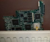
Gave it some drying time on the radiator..
20241117_143916.jpg
After this I gave it the rest of the day to dry off.
Back in the shed and hey, no change...
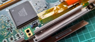
Found a little corrosion I'd missed near the keyboard connector, just a veer or 2 with some blue in. Still had continuity to the other side of the board so wasn't too concerned.... but what does concern me is the Toshiba 187hp chip is the warmest chip on the mainboard.
20241117_172255.jpg
Not as warm as the Yamaha chip on the soundboard, I measured that at 44 degrees c.
I think the smd chips are leaky and I get no sound... but I do get a slight pop at power on through the headphone jack. Tried a different speaker but still no sound.
Anyway I tried the diagnostic card again and this time my code was..
- 00
01 00
02 ff
03 01
04 00
These codes can change but always ff's and 00's.
May have to remove the keyboard connector in case of any hidden corrosion or the 187hp chip incase it's the problem.
Anybody checked the temperature on a working board or know if this is reasonable. CPU and big chips on the rear of the board stay stone cold. Guessing power isn't being supplied or enabled.
I'll keep digging around. Thanks for looking in. Any input appreciated.
 
I spy a fake tantalum (electrolytic). The purple brick on the top of the board. If it is a electrolytic, it needs to go.
 
Back
Top